Announcement

Collapse
No announcement yet.

electrical experts?

Collapse
X
  • Filter
  • Time
  • Show
Clear All
new posts

  • #16
    That is identical to my setup. I have six small switches in the ashtray to run the e cutout, both fans, fuel pump, and antenna defeat. The fuel pump and the fans are all relay controlled, so you are switching an amp or so to run (ground) the relay coil. The e cutout is a couple amps to run the motor. I use 16 ga wire to the fan relays in the fusebox, and 14 back to the e cutout & fuel pump relay. The switches are rated at 6A/125V adn 3A/250V which is about 750W which is plenty for a small DC load. Ideally, you would to go by a DC rating of the contacts and the current draw of the load you are switching, but you mostly see that rating on relay contacts. I used these switches for about 6 years now, and they are A-OK. Also, I have about 2 feet of leads coming off the switches to a connector under the dash which makes it easy to disconnect and remove the switch panel and console. You'll be sorry if you hard wire it in with short wire.

    Comment


    • #17
      Kevin, I love the look of your setup. I like the stock looking appearance where you can hide the switches...but of course you have the monster gauges in your vents, which is also awesome Your switches are a bit higher rated than mine, but since you've had no problems in several years, I feel much safer now.

      Jeff, thanks again for the great sources. I found out the 1157 turn signal bulb uses 27 watts. And I don't know if this "trick" works, but I put the voltmeter to AC and it read 26 VAC from the ACC power source.
      Since there are 2 bulbs, 54 watts, about ~20 feet of total wire, and I'm using the same source for the e-cutout, I'll just estimate a high 100 watts total output - if both are running. So we have 100 watts, 26 VAC, 20 feet of wire. That's still 22 gage wire. That's only 3.XX amps too. So I guess everything's well within range - if I calculated it right. After driving home for ~30-40 minutes today, I felt the switch and it was cool to the touch. The DRL switch is constantly on, too. I don't know if that's one way to tell too?

      EDIT: Oops, I put the wrong turn signal bulb # and spec. It's actually #2397, 28.54 watts, 2.2 amps. But I guess that still pretty close figures.
      94 Black T/A GT, Advanced Induction 355, 3200 stall, built 4L60E, Moser 9", Baer Brakes, Shooting for 11s...

      Comment


      • #18
        Originally posted by Craig 94 TA GT
        Jeff, thanks again for the great sources. I found out the 1157 turn signal bulb uses 27 watts. And I don't know if this "trick" works, but I put the voltmeter to AC and it read 26 VAC from the ACC power source.
        Since there are 2 bulbs, 54 watts, about ~20 feet of total wire, and I'm using the same source for the e-cutout, I'll just estimate a high 100 watts total output - if both are running. So we have 100 watts, 26 VAC, 20 feet of wire. That's still 22 gage wire. That's only 3.XX amps too. So I guess everything's well within range - if I calculated it right. After driving home for ~30-40 minutes today, I felt the switch and it was cool to the touch. The DRL switch is constantly on, too. I don't know if that's one way to tell too?

        EDIT: Oops, I put the wrong turn signal bulb # and spec. It's actually #2397, 28.54 watts, 2.2 amps. But I guess that still pretty close figures.
        LOL from spurt to expert in 24 hours.
        2002 Electron Blue Vette, 1SC, FE3/Z51, G92 3.15 gears, 308.9 RWHP 321.7 RWTQ (before any mods), SLP headers, Z06 exhaust, MSD Ignition Wires, AC Delco Iridium Spark Plugs, 160 t-stat, lots of ECM tuning

        1995 Z28, many mods, SOLD

        A proud member of the "F-Body Dirty Dozen"

        Comment


        • #19
          LOL All I knew before was...if it don't catch on fire, it's good! You've been a great help!!!
          94 Black T/A GT, Advanced Induction 355, 3200 stall, built 4L60E, Moser 9", Baer Brakes, Shooting for 11s...

          Comment


          • #20
            Originally posted by Jeff 95 Z28
            It depends on the current pull of the device you want to switch.
            Here is how you figure it.
            amps times volts equals watts
            so to refigure what that switch is rated at for 12 volts you have to do a little math.
            3amps X 120 volts = 360 watts
            360 watts / 12 volt = 30 amps
            More than likely your answer is yes.
            Techinically (sp) the math is correct, but the logic is not. It appears to me that you are assuming that the switch allows 360 watts of power to pass, but this isn't the case. The switch allows current to pass, it doesn't care how much power is dissipated on the other side of it. The resistance of the switch is the same whether the application is 120 AC or 12 DC. If you increase the current by a factor of ten, then you'll increase the heat dissipated by the switch by a factor of 10 as well.

            A 120v switch rated for 3 amps shouldn't be used for muct more than 3 amps at 12v DC, in fact I wouldn't go over that in a commercial product. If its something you're doing for you're own personal use then you can exceed specs by a bit usually.

            And the reason for rating with voltages has to do with arcing and safety for the manufacturers protection.

            One more thing to keep in mind is you loose current more at lower voltages in your wire runs. I can't remember the current loss verses wire gage verses length. If you have a devise that pulls 30 amps and you have say 0 gage wire with a length of 1 inch to the switch, the switch is going to have 30 amps going through it. If you have 100 feet of 0 gage wire between the switch and the 30 amp object the switch is going to see a lot more current running through it than 30 amps. This is the reason the power companies raises the voltage to run power line long distances.
            http://www.angelfire.com/pa/baconbacon/page2.html
            And I don't know what you're saying here, I suppose you're technically correct that you lose current in longer runs but the current loss is proportional to the voltage. Its much easier to think of it as voltage loss. And most objects will draw less current with a longer wire, not more. The devices that pull more current are items such as speed controlled motors. A controller monitors the speed of the motor and senses that its moving slower (because of the lower voltage) so it adjusts its driver to allow more current through it so that it gets the necessary power.

            2003 Nissan Sentra SE-R Spec-V

            PROJECT: Firebird '68 Firebird Convertible // 455 Engine // 389 Tri-Power Intake // 4 Speed Manual Trans

            Comment


            • #21
              Originally posted by Noggin
              Techinically (sp) the math is correct, but the logic is not. It appears to me that you are assuming that the switch allows 360 watts of power to pass, but this isn't the case. The switch allows current to pass, it doesn't care how much power is dissipated on the other side of it. The resistance of the switch is the same whether the application is 120 AC or 12 DC. If you increase the current by a factor of ten, then you'll increase the heat dissipated by the switch by a factor of 10 as well.

              A 120v switch rated for 3 amps shouldn't be used for muct more than 3 amps at 12v DC, in fact I wouldn't go over that in a commercial product. If its something you're doing for you're own personal use then you can exceed specs by a bit usually.

              And the reason for rating with voltages has to do with arcing and safety for the manufacturers protection.


              And I don't know what you're saying here, I suppose you're technically correct that you lose current in longer runs but the current loss is proportional to the voltage. Its much easier to think of it as voltage loss. And most objects will draw less current with a longer wire, not more. The devices that pull more current are items such as speed controlled motors. A controller monitors the speed of the motor and senses that its moving slower (because of the lower voltage) so it adjusts its driver to allow more current through it so that it gets the necessary power.
              That is not true. The rule is called ohms law. http://education.yahoo.com/reference...entry?id=34826 . Go get your a ham radio license. It's part of the test for the technicians class. Believe what you want to believe. I'm not getting into an argument about this
              2002 Electron Blue Vette, 1SC, FE3/Z51, G92 3.15 gears, 308.9 RWHP 321.7 RWTQ (before any mods), SLP headers, Z06 exhaust, MSD Ignition Wires, AC Delco Iridium Spark Plugs, 160 t-stat, lots of ECM tuning

              1995 Z28, many mods, SOLD

              A proud member of the "F-Body Dirty Dozen"

              Comment


              • #22
                I agree its not worth arguing over, but I have a 4 year degree in computer engineering (which is basically the same as electrical engineering but with a lot more digital classes) and I have 4 semesters of experience as a co-op and have been employed 14 months with the job title of "Electrical Engineer." And I'm not in maintenance.

                But thats enough chest beating from both of us.

                2003 Nissan Sentra SE-R Spec-V

                PROJECT: Firebird '68 Firebird Convertible // 455 Engine // 389 Tri-Power Intake // 4 Speed Manual Trans

                Comment


                • #23
                  The longer the wire is, the more resistance it will have, and the more it heats up, the higher the resistance will go because it is a positive coefficient. Think of the wire as a resistor in the circuit and it will make more sense to you. A thin wire can flow less electrons (amps) just as a small diameter fuel line can only flow so much fuel. If the voltage tries to push too many amps thru a small wire it heats up, resistance goes up, and causes less current to flow in the loop. The effect is less pronounced for a short wire because there is less resistance. So, if you have a long length of wire, and the wire has too much resistance from insufficient cross section and also from heat, you will get a voltage drop. This is why some fuel pump controllers boost the voltage to get the correct voltage back to the fuel pump instead of starting out with 13.5 or so and dropping a couple volts (poor grounding is also high resistance). Also why sometimes there is more voltage measured at the battery and alternator than at the dash or cigarette lighter, or back by the tail lights. Big wire is your friend, except that it is expensive, bulky, and heavy. All this is why cars might go to a 48V system in the future. You can then use small dia wire, small switches, small relays to run your power because it takes less current. Just have to make sure insulation is adequate for the higher voltage (as was mentioned above).

                  Comment


                  • #24
                    Hey guys, I hate to bring this topic back up again, but I'm having a problem with the LED wiring to the switches. The e-cutout wiring works fine (described in the diagram), but the fan switch wiring doesn't light up 1 LED.


                    When the switch lever is facing this way: <-- (or to the right internally), the low speed fans kick on and the yellow LED lights up correctly. When switch is --> (or left internally), the high speed fans kick on, but the Green LED doesn't work. I've tried every combo using the green LED terminals on all the switch terminals, but no combination seems to work. I've also tried hooking it to a separate power source, then use a ground in the switch, but it lights up all the time. Does anyone know what I'm doing wrong in the diagram? These LEDs have become a real PITA for me because I've already blown 3 fuses doing the e-cutout and DRL LEDs
                    Thanks in advance.
                    94 Black T/A GT, Advanced Induction 355, 3200 stall, built 4L60E, Moser 9", Baer Brakes, Shooting for 11s...

                    Comment


                    • #25
                      I haven't messed around with building electronics in years so I'm not sure what is available now. It used to be LEDs were like 3 volts. Anything more than like 5 volts would blow them. I blew a pile of them up trying to make a bar graph tach one time. Do they make 12 volt LEDs now? Are you sure the green LED still works and hasn't been blown? I assume you know that the LEDs have a polarity to them.
                      2002 Electron Blue Vette, 1SC, FE3/Z51, G92 3.15 gears, 308.9 RWHP 321.7 RWTQ (before any mods), SLP headers, Z06 exhaust, MSD Ignition Wires, AC Delco Iridium Spark Plugs, 160 t-stat, lots of ECM tuning

                      1995 Z28, many mods, SOLD

                      A proud member of the "F-Body Dirty Dozen"

                      Comment


                      • #26
                        Jeff, the LEDs are properly working. I think the problem is the way the fan switch is wiring...not that anything is wrong, but I found the diagram, and I think it would probably work if I follow it. Also, the green LEDs I'm using are 12v, which is impressive because I can't even see a resistor in it (although it claims to have one built in). It works on all other circuits. The yellow LEDs are only 2.5-3V, so I bought a few 680 Ohm resistors.
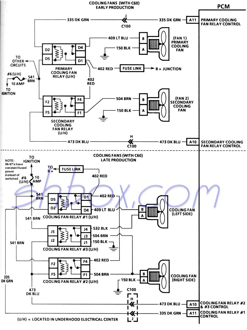
                        Here is the diagram for the fan switch:

                        I think it should work
                        94 Black T/A GT, Advanced Induction 355, 3200 stall, built 4L60E, Moser 9", Baer Brakes, Shooting for 11s...

                        Comment


                        • #27
                          Does this help from Rob's web site? Which one is yours?
                          2002 Electron Blue Vette, 1SC, FE3/Z51, G92 3.15 gears, 308.9 RWHP 321.7 RWTQ (before any mods), SLP headers, Z06 exhaust, MSD Ignition Wires, AC Delco Iridium Spark Plugs, 160 t-stat, lots of ECM tuning

                          1995 Z28, many mods, SOLD

                          A proud member of the "F-Body Dirty Dozen"

                          Comment


                          • #28
                            Thanks for the diagram Jeff. I have no idea which one I have because the fan switch is SLP's. I'll have to examine it further under the hood and such. But I'm sure when I figure it out, I can connect the LEDs to the correct spots.
                            94 Black T/A GT, Advanced Induction 355, 3200 stall, built 4L60E, Moser 9", Baer Brakes, Shooting for 11s...

                            Comment


                            • #29
                              That diagram in black makes sense and looks like it should work and that's quite a bit different than the one you drew up. As soon as you bring the dark green (low fan relay) to ground (switch position 1) the lower LED lights up and when you bring the dark blue and dark green wire to ground (fans on high - switch position 2), both LEDs should light.

                              Comment


                              • #30
                                OK thanks Kevin. I will try to rewire them asap. My original diagram is a bit confusing because I had no idea what each wire did...all I knew was that it went into the PCM harness supplied by SLP. But I guess 3 of them are gnd, and the dark green/dark blue are different.
                                94 Black T/A GT, Advanced Induction 355, 3200 stall, built 4L60E, Moser 9", Baer Brakes, Shooting for 11s...

                                Comment

                                Working...
                                X